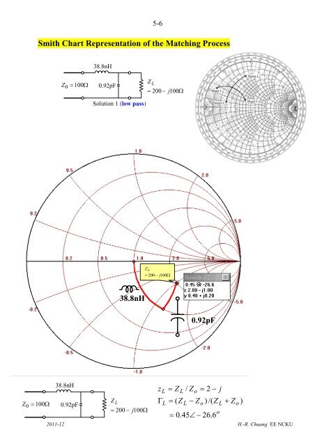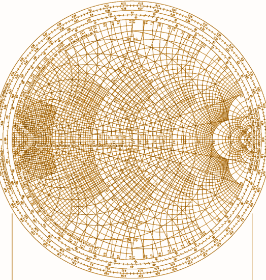


Smith Chart Impedances, voltages, currents, etc. all still have the same properties, but the results can be generalized to any line with the same normalized impedances The Smith Chart is a clever tool for analyzing transmission lines The outside of the chart shows location on the line in wavelengths The combination of intersecting circles inside the chart allow us to locate the normalized impedance and then to find the impedance anywhere on the line all repeat every half wavelength The magnitude of the reflection coefficient, the standing wave ratio (SWR) do not change, so they characterize the voltage & current patterns on the line If the load impedance is normalized by the characteristic impedance of the line, the voltages, currents, impedances, etc. X=1/3 x=1 x=2.5 x=-1/3 x=-1 x=-2.There are many methods for impedance matching in your circuits. One popular method for plotting impedance and determining impedance matching is to use a Smith chart. Impedance matching in this PCB can be determined using a Smith chart Once impedance matching requirements are determined, the results can be simulated in a SPICE-based simulation application. High speed and high frequency systems need impedance matching to ensure efficient power transfer and prevent reflections. In many cases, you need to measure and carefully simulate the appropriate impedance required to ensure impedance matching and prevent power reflection. In some cases, such as with transmission line stub matching in RF circuits or input impedance matching to a feedline’s characteristic impedance, a graphical representation of impedance can aid impedance matching.Ī Smith chart provides just such a graphical representation of impedance, and it is a useful tool for understanding how impedance varies in different systems.


 0 kommentar(er)
